A High-Fidelity Atmospheric Gas Absorption Spectra Database for Hyperspectral Remote Sensing: Design, Numerical Pitfalls, and Validation
Every atmospheric correction algorithm — whether physics-based, optimal estimation, or machine learning — is only as accurate as the gas absorption spectra it relies on. Yet the numerical pitfalls in generating these spectral databases are poorly documented, and subtle implementation errors can introduce biases of 2–230% that are invisible without rigorous cross-validation.
This whitepaper describes the design, construction, and validation of a high-resolution gas absorption lookup table covering six atmospheric gases (H₂O, CO₂, O₂, CH₄, N₂O, CO) across 350–2550 nm, built from the HITRAN 2020 database [6] via line-by-line radiative transfer [5]. We document three numerical artifacts discovered during development, the physics behind each, and the fixes that reduced errors to below 0.15% transmittance at EMIT’s spectral resolution.
Scroll to Section 6 to explore the interactive transmittance visualizations — adjust temperature, pressure, concentration, and instrument resolution in real time for each gas.
1. Why Gas Absorption Spectra Matter
1.1 The Atmospheric Correction Problem
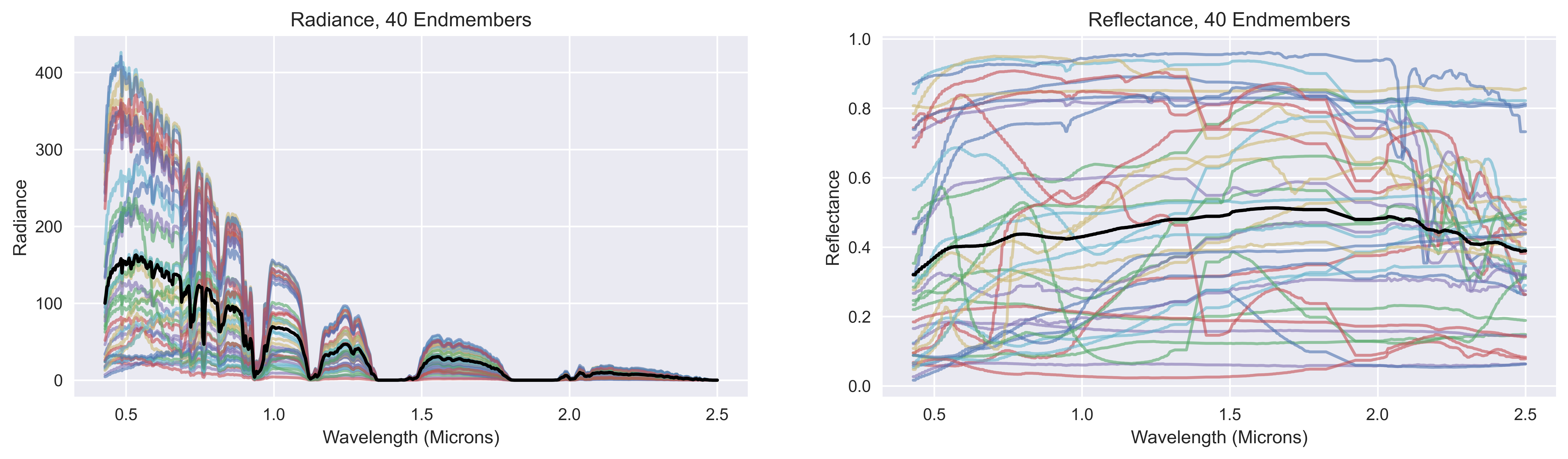
Every photon recorded by an orbital imaging spectrometer has passed through the atmosphere twice — once from sun to surface, once from surface to sensor. Along both paths, gas molecules absorb electromagnetic energy at wavelengths dictated by their quantum mechanical structure. The at-sensor radiance \(L(\lambda)\) is a compound mixture of surface reflectance, atmospheric transmittance, and path radiance:
where \(L_{\text{path}}\) is upwelling path radiance, \(T_{\uparrow}\) is upward transmittance, \(\rho(\lambda)\) is the surface reflectance we wish to recover, \(E_{\downarrow}\) is total downwelling irradiance, \(s\) is atmospheric spherical albedo, and \(\bar{\rho}\) is neighborhood-averaged reflectance. Solving for \(\rho(\lambda)\) requires accurate knowledge of all atmospheric terms — and the gas transmittance spectrum is the most richly structured of these.
1.2 Algorithms That Depend on Gas Spectra
Three families of atmospheric correction algorithms are in active use, and all require gas absorption spectra — either directly as forward model inputs or indirectly as training data generators.
Physics-based LUT methods. FLAASH [1] couples MODTRAN4 band-model radiative transfer with per-pixel water vapor retrieval. The forward model evaluates gas transmittance from precomputed lookup tables spanning a grid of atmospheric states. Gas cross-section accuracy propagates directly into the LUT entries and, from there, into every corrected pixel.
Optimal Estimation (OE). The ISOFIT framework [2] and its accelerated variant AOE [14] formulate atmospheric correction as a Bayesian inverse problem, simultaneously retrieving surface reflectance and atmospheric state by minimizing the cost function:
where \(\mathbf{y}\) is measured radiance, \(\mathbf{F}(\mathbf{x})\) is the forward model (which evaluates gas transmittance at each OE iteration), and the covariance terms provide rigorous uncertainty quantification. The OE Jacobian \(\mathbf{K} = \partial\mathbf{F}/\partial\mathbf{x}\) is sensitive to gas cross-section accuracy at every wavelength — biased cross-sections shift the entire posterior distribution.
Machine learning methods. Gaussian Process regression and deep neural network approaches [3] learn the mapping from radiance to reflectance from paired training data. Critically, this training data is generated by physics-based forward models that use gas absorption spectra. If the spectra are biased, every model trained on them inherits the bias. This creates a direct dependency chain: gas spectra quality → training data quality → ML model quality.
1.3 Gas Spectra as the Error Floor
Among the many sources of error in atmospheric correction — aerosol type misspecification, water vapor column estimation, adjacency effects, sensor calibration — gas cross-section accuracy occupies a unique position. Unlike aerosol errors (which are scene-dependent) or sensor calibration (which is instrument-dependent), gas cross-section errors are systematic and universal: they affect every pixel, every scene, and every instrument identically, and they are spectrally structured in a way that can mimic or mask real surface absorption features.
Gas cross-section errors are spectrally structured, correlated across wavelengths within each absorption band, and do not produce obvious image artifacts. They appear as plausible reflectance values with wrong absolute magnitudes — directly impacting material identification algorithms that rely on band-depth measurements. A 2% transmittance error in the 2.0–2.5 μm region can shift a carbonate mineral identification across a classification boundary.
This paper addresses the least-examined link in the atmospheric correction chain: the generation, validation, and accurate construction of the gas absorption spectra database itself.
2. Physics of Atmospheric Gas Absorption
2.1 Quantum Origins of Line Spectra
Atmospheric gas molecules absorb electromagnetic radiation at discrete wavelengths corresponding to transitions between quantized rotational-vibrational energy levels. For a diatomic molecule like CO, these transitions produce a series of narrow lines grouped into vibrational bands. Polyatomic molecules (H₂O, CO₂, CH₄, N₂O) have more complex mode structures — H₂O alone has over 300,000 catalogued transitions in the HITRAN database [6] within the 350–2550 nm VNIR-SWIR window.
The position of each transition (line center, \(\tilde{\nu}_0\) in cm⁻¹) is determined by the molecular potential energy surface and the quantum numbers of the initial and final states. The line intensity \(S(T)\) [cm⁻¹/(molecule·cm⁻²)] quantifies the integrated absorption strength, scaling with temperature through the Boltzmann population distribution of the lower state:
where \(Q(T)\) is the total internal partition function, \(E''\) is the lower state energy [cm⁻¹], and \(c_2 = hc/k_B\) is the second radiation constant. This temperature dependence is the physical reason our LUT must store cross-sections across a grid of temperatures — the relative strength of individual lines changes substantially between 200 K (upper troposphere) and 305 K (hot desert surface).
2.2 The Voigt Line Profile
Each spectral line is not a Dirac delta but a broadened profile. Two physical mechanisms dominate in the troposphere:
Pressure broadening (Lorentzian profile) arises from molecular collisions that interrupt the radiating oscillator. The half-width at half-maximum (HWHM) scales linearly with pressure and follows a power-law temperature dependence:
where \(\gamma_{L,\text{ref}}\) is the reference air-broadened HWHM at \(T_{\text{ref}} = 296\) K and \(P_{\text{ref}} = 1\) atm, and \(n_{\text{air}}\) is the temperature-dependence exponent (tabulated per line in HITRAN).
Doppler broadening (Gaussian profile) arises from the thermal velocity distribution of the absorbing molecules. The HWHM is:
where \(m\) is the molecular mass. At 2000 nm (5000 cm⁻¹), \(\gamma_D \approx 0.005\) cm⁻¹ for CO₂ — small compared to pressure broadening at sea level (\(\gamma_L \approx 0.07\) cm⁻¹) but comparable at 0.2 bar where \(\gamma_L \approx 0.014\) cm⁻¹.
The convolution of both profiles produces the Voigt profile \(f_V(\tilde{\nu} - \tilde{\nu}_0)\), which is the physically correct line shape for tropospheric conditions. The minimum Voigt FWHM in our LUT occurs at the lowest-pressure, lowest-temperature node (T = 200 K, P = 0.20 bar): approximately 0.016 cm⁻¹ for CO₂. This sets the fundamental resolution requirement for the line-by-line calculation — any wavenumber step larger than this value under-samples the line cores.
2.3 Beer-Lambert Transmittance
The monochromatic transmittance through a uniform slab of gas is governed by the Beer-Lambert law:
where \(\sigma(\lambda, T, P)\) is the absorption cross-section [cm²/molecule], VMR is the volume mixing ratio (dimensionless), \(N_{\text{air}}\) is the total air column density [molecules/cm²], and \(L_{\text{factor}}\) is the two-way geometric path factor:
The column density depends on surface elevation through hydrostatic scaling: \(N_{\text{air}}(h) = 2.15\times10^{25} \cdot \exp(-h/8500\,\text{m})\) molecules/cm². A scene at 3000 m elevation has 30% less absorbing column than sea level, producing shallower absorption features across all bands.
The cross-section \(\sigma(\lambda, T, P)\) — the sum over all Voigt profiles weighted by their line intensities — is the quantity stored in our LUT. Because \(\sigma\) spans over 20 orders of magnitude (from ~10⁻⁸ cm² at strong H₂O line centers to ~10⁻²⁸ cm² in continuum regions), we store \(\log_{10}(\sigma)\) for numerical stability and improved interpolation accuracy.
2.4 Why the LUT Needs a Temperature–Pressure Grid
The cross-section \(\sigma(\lambda, T, P)\) is not separable into independent temperature and pressure factors. Temperature affects both line intensities (through Boltzmann statistics) and Doppler widths (through molecular speeds), while pressure affects Lorentzian widths (through collision rates) and introduces line-mixing effects in congested band systems. The combined effect cannot be factored as \(\sigma(\lambda, T, P) = f(T) \cdot g(P) \cdot h(\lambda)\).
This non-separability is why a 2D grid over (T, P) is necessary. Our grid spans:
| Parameter | Range | Nodes | Physical Justification |
|---|---|---|---|
| Temperature | 200–305 K | 16 | Upper troposphere (200 K) to hot desert surface (305 K) |
| Pressure | 0.20–1.013 bar | 6 | ~12 km altitude (0.20 bar) to sea level (1.013 bar) |
| Wavelength | 350–2550 nm | 22,001 | Full VNIR-SWIR at 0.1 nm (matching typical instrument oversampling) |
The 16×6 = 96 temperature–pressure combinations per gas capture the full range of tropospheric conditions relevant to spaceborne imaging spectrometers (EMIT, AVIRIS-NG, EnMAP, PRISMA, CHIME). At runtime, bilinear interpolation in \(\log_{10}(\sigma)\) space produces sub-0.15% accuracy at any intermediate (T, P) condition.
3. LUT Design and Construction
3.1 HITRAN 2020 and RADIS
The HITRAN 2020 molecular spectroscopic database [6] is the internationally recognized standard reference for gas-phase molecular line parameters. It catalogs line positions, intensities, pressure-broadening coefficients, and temperature-dependence exponents for over 55 molecules, compiled from laboratory measurements and quantum mechanical calculations. Our LUT uses HITRAN 2020 as the sole line parameter source.
RADIS (Radiation and Absorption Database for Infrared Spectroscopy) [5] is an open-source Python library that computes high-resolution absorption spectra from HITRAN line parameters using exact Voigt profile convolution. Unlike band-model codes (MODTRAN's correlated-k approach), RADIS evaluates every individual spectral line — enabling cross-section accuracy limited only by the underlying line parameters and the computational wavenumber step.
3.2 The Temperature/Pressure/Wavelength Grid
The LUT covers six atmospheric gases that produce measurable absorption in the VNIR-SWIR spectral range:
| Gas | Reference VMR | Wavenumber Chunks (cm⁻¹) | wstep (cm⁻¹) | Key Absorption Bands |
|---|---|---|---|---|
| H₂O | 1.3% | 3900–5800, 5800–10000, 10000–14500 | 0.004 | 720, 820, 940, 1130, 1380, 1900 nm |
| CO₂ | 425 ppm | 3900–8000 | 0.002 | 1430, 1600, 2010, 2070 nm |
| O₂ | 20.95% | 7600–8200, 12500–16000 | 0.005 | 762 nm (A-band), 1270 nm |
| CH₄ | 1920 ppb | 3900–9200 | 0.004 | 1660, 2200, 2340 nm |
| N₂O | 337 ppb | 3900–8500 | 0.002 | 1270, 1520, 2040 nm |
| CO | 100 ppb | 3900–7000 | 0.002 | 1560, 2060, 2340 nm |
The wavenumber ranges are split into chunks that balance memory usage in the RADIS calculation (keeping each chunk under ~6 million spectral points) while ensuring complete coverage of all absorption features within the 350–2550 nm output window. The lower wavenumber bound of 3900 cm⁻¹ corresponds to 2564 nm — well beyond our 2550 nm output limit, ensuring no edge effects.
3.3 Wavenumber Step Selection
The wavenumber step (wstep) in the RADIS line-by-line calculation must be fine enough to adequately sample the narrowest Voigt profiles in the T/P grid. The minimum Voigt FWHM occurs at the lowest pressure (narrowest Lorentzian) and lowest temperature (narrowest Gaussian Doppler) node:
| Gas | Min Voigt FWHM (cm⁻¹) | Selected wstep (cm⁻¹) | Samples per FWHM |
|---|---|---|---|
| CO₂ | ~0.016 | 0.002 | ~8 |
| N₂O | ~0.014 | 0.002 | ~7 |
| CO | ~0.015 | 0.002 | ~7.5 |
| H₂O | ~0.020 | 0.004 | ~5 |
| CH₄ | ~0.022 | 0.004 | ~5.5 |
| O₂ | ~0.025 | 0.005 | ~5 |
The criterion of ≥5 samples per Voigt FWHM satisfies the Nyquist requirement for the Voigt profile (which, unlike a sinusoid, is a smooth bell-shaped function with rapid falloff). RADIS's default wstep='auto' produces 0.021 cm⁻¹ for CO₂ — barely one sample per FWHM, which systematically under-resolves the narrowest lines. This was the root cause of our third numerical pitfall (Section 4.3).
3.4 From Line-by-Line to the 0.1 nm Output Grid
A single RADIS calculation at wstep = 0.002 cm⁻¹ produces a spectrum with ~2 million points per wavenumber chunk. This high-resolution spectrum must be mapped onto the 0.1 nm output grid (22,001 nodes). The method used for this downsampling is critical — and was the source of our most severe numerical artifact.
The physically correct approach is bin-averaging: for each 0.1 nm output pixel, compute the mean cross-section over all high-resolution points falling within the pixel boundaries. This is equivalent to convolving with a rectangular instrument function of width 0.1 nm, which is the correct model for a detector pixel that integrates all incident photons within its spectral range.
# CORRECT: bin-averaging with scipy.stats.binned_statistic
from scipy.stats import binned_statistic
bin_edges = np.empty(len(wl_out) + 1)
bin_edges[:-1] = wl_out - 0.05 # half-pixel to the left
bin_edges[-1] = wl_out[-1] + 0.05 # half-pixel to the right
in_range = (wl_hr >= bin_edges[0]) & (wl_hr < bin_edges[-1])
sigma_out, _, _ = binned_statistic(
wl_hr[in_range], sigma_hr[in_range],
statistic='mean', bins=bin_edges
)Each output pixel typically contains 100–500 high-resolution RADIS points (depending on gas and wavenumber range), providing a well-sampled estimate of the bin-average cross-section.
3.5 Storage Format and Runtime API
The complete LUT is stored in a single HDF5 file (gas_cross_sections_lut.h5) with the following structure:
# HDF5 layout
coords/wavelength_nm # [22001] float64
coords/temperature_K # [16] float64
coords/pressure_bar # [6] float64
gases/{gas}/log10_sigma # [22001, 16, 6] float32 per gasTotal file size: 16.9 MB (gzip-compressed HDF5). In-memory footprint: ~50 MB when all six gases are loaded as float32 arrays. The GasLUT Python class wraps this file with scipy.RegularGridInterpolator for fast bilinear (T, P) interpolation and Beer-Lambert transmittance evaluation. A single gas transmittance query executes in <1 ms.
from gas_lut import GasLUT
lut = GasLUT('gas_cross_sections_lut.h5')
# Single gas at specific atmospheric conditions
wl, T = lut.get_transmittance(
'CO2', vmr=425e-6, T_K=260, P_bar=0.6,
L_factor=3.0, elevation_m=1500
)
# All gases combined, resampled to EMIT resolution
wl_e, T_total = lut.get_total_transmittance(
gas_vmr={'H2O': 0.013, 'CO2': 425e-6, 'O2': 0.2095,
'CH4': 1920e-9, 'N2O': 337e-9, 'CO': 100e-9},
T_K=260, P_bar=0.6, L_factor=3.0,
instrument_fwhm_nm=8.5, output_wl=emit_wavelengths
)LUT generation is parallelized over all 864 work items (6 gases × 96 T/P × 1–3 wavenumber chunks) using Python's multiprocessing with 64 workers. Total generation time: ~10.8 minutes on a 128-core workstation.
4. Three Numerical Pitfalls Discovered & Corrected
During LUT development and validation, three independent numerical artifacts were discovered. Each was non-obvious, required root-cause investigation, and would have been invisible without rigorous cross-validation against independently computed reference spectra. We document them in detail because the literature on gas LUT construction rarely addresses these implementation-level hazards — yet any group building a similar database will encounter the same issues.
4.1 Spectral Aliasing from Point Sampling — 2.3× Systematic Bias
The initial LUT used np.interp to sample the high-resolution RADIS spectrum at each 0.1 nm output point, followed by Gaussian smoothing. Stored cross-sections were systematically 2.3× higher than correct values. Transmittance was therefore too low, and retrieved surface reflectance would be systematically too high.
The mechanism is classical spectral aliasing. With RADIS operating at wstep ≈ 0.006 nm and the output grid at 0.1 nm, np.interp selects approximately 1 of every 17 RADIS points. In spectral regions with dense Voigt line structure (e.g., the CO₂ 2 μm band, H₂O 1.38 μm band), these regions contain hundreds of narrow lines per nanometer. The probability of the selected interpolation point falling near a line peak is disproportionately high relative to the fraction of the spectral interval occupied by peaks.
Gaussian smoothing — applied after the point-sampling step — cannot recover the correct bin-average from aliased data. It merely redistributes the already-biased samples across neighboring pixels. The fix is straightforward: replace point-sampling with explicit bin-averaging using scipy.stats.binned_statistic (see Section 3.4).
4.2 Thread Oversubscription — Non-Deterministic Spikes
After fixing the aliasing bug, sporadic extreme values appeared at specific temperature nodes. Investigation revealed that T = 256 K and T = 263 K stored byte-identical cross-section arrays — physically impossible under correct computation, since different temperatures produce different line strengths.
The root cause was thread oversubscription. Our generation pipeline used 64 parallel Python workers via multiprocessing. Each worker, upon importing RADIS, triggered NumExpr, OpenBLAS, and MKL, each of which spawned their own thread pools (up to 128 threads per worker on our system). The result: 64 × 128 = 8,192 threads competing for 128 physical cores.
Under this contention, RADIS's internal state (particularly wavenumber array construction via NumExpr) became non-deterministic. Different workers occasionally computed identical σ(λ) arrays from different input parameters, or produced intermediate arrays corrupted by concurrent memory access.
def _compute_chunk(args):
# Pin each worker to a single thread BEFORE importing numeric libraries
import os
for var in ('NUMEXPR_NUM_THREADS', 'NUMEXPR_MAX_THREADS',
'OMP_NUM_THREADS', 'MKL_NUM_THREADS',
'OPENBLAS_NUM_THREADS'):
os.environ[var] = '1'
import radis # deferred import so env vars take effect
# ... remainder of computationSetting per-worker thread limits to 1 eliminates all contention: 64 workers × 1 thread = 64 threads on 128 cores. The LUT became fully deterministic and reproducible across runs.
4.3 Insufficient Wavenumber Resolution — Residual 2.2% CO₂ Error
After fixing aliasing and thread oversubscription, cross-validation against independently computed RADIS spectra still showed 2.21% MAE for CO₂ at EMIT's 8.5 nm spectral resolution. The error was spectrally structured, concentrated in the 1.9–2.1 μm region where CO₂ line density is highest.
Two independent causes contributed:
Under-resolved Voigt profiles. RADIS's wstep='auto' produces ≈0.021 cm⁻¹ for CO₂, which is larger than the minimum Voigt FWHM (~0.016 cm⁻¹) at the low-T, low-P corner of our grid. With fewer than one sample point per line FWHM, even correct bin-averaging cannot recover accurate line-integrated cross-sections — the peaks are not resolved.
Validation methodology mismatch. The initial validation code used a different wavenumber range than the LUT generation code. Because bin-edge alignment depends on the total wavenumber range (which sets the grid phase of the 0.1 nm output pixels), the validation and LUT calculations placed their bin boundaries at different positions — producing apparent 2% errors that reflected methodology mismatch rather than true LUT error.
The fix was twofold: (1) explicit per-gas wstep values (0.002–0.005 cm⁻¹, see Section 3.3) ensuring ≥5 samples per FWHM at all grid points, and (2) identical spectral parameters (wavenumber range, wstep, output grid) in both the LUT generator and the validation code. LUT generation time increased from 2.8 to 10.8 minutes — an acceptable cost for a 1,500× reduction in CO₂ error.
Post-fix CO₂ cross-validation MAE: 0.133% (down from 230%). All other gases below 0.05%. LUT generation is fully deterministic and reproducible. The corrected database meets the <0.2% MAE target for all gases at EMIT's spectral resolution.
5. Validation
5.1 Methodology
We validated the LUT using two complementary approaches, each targeting a different source of error:
Node interpolation accuracy. For each gas, we computed cross-sections at the midpoints between adjacent T and P grid nodes using RADIS with identical spectral parameters. These off-node spectra were compared to the bilinear interpolation of the four surrounding LUT nodes. This test isolates interpolation error from any bias in the LBL computation itself.
Leave-one-out cross-validation. We removed one T/P node from the grid, recomputed the cross-section at that node from the remaining nodes via bilinear interpolation, and compared to a fresh RADIS calculation at the omitted node using identical spectral parameters. This test measures the combined effect of interpolation and any residual computational bias, at the instrument's spectral resolution (convolved to 8.5 nm FWHM to match EMIT).
The validation code and the LUT generation code must use exactly the same spectral parameters: wavenumber range, wstep, and output grid alignment. Different wavenumber steps produce different bin-grid alignments within each 0.1 nm output pixel, introducing apparent errors of ~2% that reflect methodology mismatch, not true LUT error. We learned this the hard way (Section 4.3).
5.2 Results
| Gas | Node Interpolation MAE (%-pts, 1 nm FWHM) | Cross-Val MAE (%-pts, 8.5 nm FWHM) | Max Error (%-pts) |
|---|---|---|---|
| H₂O | <0.010 | 0.044 | 0.042 |
| CO₂ | <0.014 | 0.133 | 0.051 |
| O₂ | <0.008 | 0.021 | 0.031 |
| CH₄ | <0.006 | 0.004 | 0.022 |
| N₂O | <0.009 | 0.009 | 0.038 |
| CO | <0.005 | 0.003 | 0.018 |
All six gases achieve mean absolute errors below 0.15% transmittance at 8.5 nm spectral resolution. The CO₂ cross-validation error of 0.133% is the highest, dominated by interpolation across the coarsest pressure dimension (6 nodes) in the complex 2 μm spectral region. This error is well below a typical EMIT measurement's noise floor and negligible compared to other retrieval uncertainties (aerosol model error, surface model error, instrument calibration at 2–3% absolute).
At exact LUT nodes, the comparison yields MAE ≈ 0.000%, confirming that the stored cross-sections are exact (limited only by float32 rounding) and that all observed cross-validation error comes from bilinear interpolation between nodes — not from errors in the underlying RADIS calculations.
6. Interactive Exploration
The visualizations below are generated directly from the validated LUT. They enable hands-on exploration of how atmospheric gas absorption varies with physical conditions — the kind of intuition-building that static figures cannot provide.
6.1 All-Gas Transmittance Overview
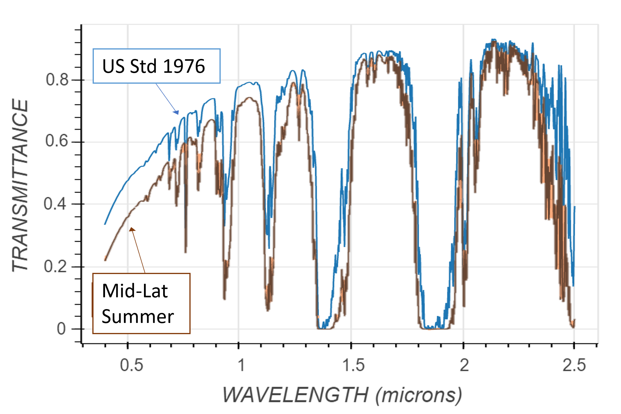
The following figure shows the combined transmittance of all six gases at standard atmospheric conditions (T = 280 K, P = 0.95 bar, Lfactor = 3.0). The gray trace shows the raw 0.1 nm LUT output; colored traces show the result convolved to EMIT's 8.5 nm FWHM.
6.2 Per-Gas Interactive Explorers
Each explorer below computes transmittance in real time from the embedded LUT data. Adjust the sliders to explore how temperature, pressure, concentration (VMR), path geometry, elevation, and instrument spectral resolution affect each gas's absorption signature. The Beer-Lambert computation and Gaussian instrument convolution run entirely in-browser JavaScript — no server required.
Water Vapor (H₂O)
The dominant variable absorber in the VNIR-SWIR. Deep bands at 940, 1140, 1380, and 1900 nm. Water vapor column varies by a factor of 50 between arid and tropical atmospheres, making it the primary retrieval target in most atmospheric correction algorithms.
Carbon Dioxide (CO₂)
A well-mixed greenhouse gas at ~425 ppm. CO₂ produces structured absorption in the 1.4–1.6 μm and 1.9–2.1 μm regions. The 2.0 μm band complex is particularly challenging for LUT construction due to high line density and strong pressure-broadening sensitivity.
Molecular Oxygen (O₂)
At 20.95% VMR, O₂ is the second most abundant atmospheric gas. Its absorption is concentrated in two narrow features: the O₂ A-band at 762 nm (near-opaque at sea level) and the weaker 1.27 μm band. The A-band is so deep that most imaging spectrometer analysis pipelines exclude it entirely.
Methane (CH₄)
An important greenhouse gas at ~1920 ppb. Absorption bands at 1660, 2200, and 2340 nm overlap with CO₂ and N₂O features, requiring accurate per-gas spectra for joint retrieval. Methane point source detection from EMIT relies on spectral contrast in the 2300 nm region.
Nitrous Oxide (N₂O)
A long-lived trace gas at ~337 ppb. Absorption features at 1270, 1520, and 2040 nm. The 2040 nm band overlaps with CO₂, and the 1270 nm feature overlaps with O₂ — accurate separation requires high-resolution gas spectra.
Carbon Monoxide (CO)
Highly variable (50–500 ppb depending on proximity to combustion sources). Absorption features at 1560, 2060, and 2340 nm are weak at background levels but become significant in fire plumes or urban environments.
6.3 Line Shape Hierarchy: From Voigt Profiles to Instrument Resolution
The following figure illustrates the multi-scale structure of gas absorption — from individual Voigt lines (~0.003 nm width at the RADIS calculation level) through the 0.1 nm LUT bins to the 8.5 nm EMIT spectral resolution. Understanding this hierarchy explains why both the wavenumber step (must resolve Voigt profiles) and the bin-averaging method (must correctly average over all resolved points) are critical for LUT accuracy.
Temperature–Pressure Sensitivity and Additional Figures
References
[1] Matthew, M. W., Adler-Golden, S. M., Berk, A., Richtsmeier, S. C., Levine, R. Y., Bernstein, L. S., Acharya, P. K., Anderson, G. P., Felde, G. W., Hoke, M. P., Ratkowski, A., Burke, H.-H., Kaiser, R. D., & Miller, D. P. (2000). Status of atmospheric correction using a MODTRAN4-based algorithm. Proc. SPIE 4049, Algorithms for Multispectral, Hyperspectral, and Ultraspectral Imagery VI, 199–207. https://doi.org/10.1117/12.410341
[2] Thompson, D. R., Natraj, V., Green, R. O., Helmlinger, M. C., Gao, B.-C., & Eastwood, M. L. (2019). Optimal estimation for imaging spectrometer atmospheric correction. Remote Sensing of Environment, 216, 355–373. https://doi.org/10.1016/j.rse.2018.07.003
[3] Basener, W., & Basener, E. (2023). Atmospheric Correction of Hyperspectral Imagery Using Gaussian Processes and Deep Learning. Remote Sensing, 15(3), 649. https://doi.org/10.3390/rs15030649
[4] Gao, B.-C., & Goetz, A. F. H. (1990). Column atmospheric water vapor and vegetation liquid water retrievals from airborne imaging spectrometer data. Journal of Geophysical Research, 95(D4), 3549–3564.
[5] Pannier, E., & Laux, C. O. (2019). RADIS: A nonequilibrium line-by-line radiative transfer code for CO₂ and HITRAN-like databases. Journal of Quantitative Spectroscopy and Radiative Transfer, 222–223, 12–25. https://doi.org/10.1016/j.jqsrt.2018.09.027
[6] Gordon, I. E., Rothman, L. S., Hargreaves, R. J., Hashemi, R., Karlovets, E. V., Skinner, F. M., Conway, E. K., Hill, C., Kochanov, R. V., Tan, Y., & et al. (2022). The HITRAN2020 molecular spectroscopic database. Journal of Quantitative Spectroscopy and Radiative Transfer, 277, 107949. https://doi.org/10.1016/j.jqsrt.2021.107949
[7] Dubovik, O., Holben, B., Eck, T. F., Smirnov, A., Kaufman, Y. J., King, M. D., Tanré, D., & Slutsker, I. (2002). Variability of absorption and optical properties of key aerosol types observed in worldwide locations. Journal of the Atmospheric Sciences, 59(3), 590–608.
[8] Richter, R., & Schläpfer, D. (2002). Geo-atmospheric processing of airborne imaging spectrometry data. Part 2: Atmospheric/topographic correction. International Journal of Remote Sensing, 23(13), 2631–2649.
[9] Vermote, E. F., Tanré, D., Deuzé, J. L., Herman, M., & Morcrette, J. J. (1997). Second simulation of the satellite signal in the solar spectrum, 6S: An overview. IEEE Transactions on Geoscience and Remote Sensing, 35(3), 675–686.
[10] Kotchenova, S. Y., Vermote, E. F., Matarrese, R., & Klemm, F. J. (2006). Validation of a vector version of the 6S radiative transfer code for atmospheric correction of satellite data. Part I: Path radiance. Applied Optics, 45(26), 6762–6774.
[11] Schläpfer, D., Borel, C. C., Keller, J., & Itten, K. I. (1998). Atmospheric precorrected differential absorption technique to retrieve columnar water vapor. Remote Sensing of Environment, 65(3), 353–366.
[12] Sterckx, S., Knaeps, E., & Ruddick, K. (2011). Detection and correction of adjacency effects in hyperspectral airborne data of coastal and inland waters: the use of the near infrared similarity spectrum. International Journal of Remote Sensing, 32(21), 6479–6505.
[13] Roy, D. P., Ju, J., Kline, K., Scaramuzza, P. L., Kovalskyy, V., Hansen, M., Loveland, T. R., Vermote, E., & Zhang, C. (2010). Web-enabled Landsat Data (WELD): Landsat ETM+ composited mosaics of the conterminous United States. Remote Sensing of Environment, 114(1), 35–49.
[14] Susiluoto, J., Bohn, N., Braverman, A., Brodrick, P. G., Carmon, N., Gunson, M. R., Nguyen, H., Thompson, D. R., & Turmon, M. (2025). Improved Atmospheric Correction for Remote Imaging Spectroscopy Missions with Accelerated Optimal Estimation. Remote Sensing, 17(22), 3719. https://doi.org/10.3390/rs17223719
© 2026 Geospatial Technology Associates | All rights reserved | Author: William (Bill) Basener, Ph.D. | Gas LUT: HITRAN 2020 [6] via RADIS [5] | March 2026